Settings
 Fast Delivery
 Payment Types


 Marketplace Product

What is a Stepper Motor?
Stepper motors differ from DC motors and servos in several ways, and their unique characteristics make them a popular choice in many DIY projects and professional applications. They excel in situations where predictable precision and strong low-RPM torque are required. However, they also have limitations and demand different handling to fully leverage their strengths. Read on to learn the basics of stepper motors, how they compare to other common motor types, what advantages and drawbacks they offer, and which projects benefit most from them.

How Stepper Motors Compare to DC Motors and Servos
DC motors are among the most common choices in maker projects. These motors offer continuous rotation, are easy to use, and are available in a wide range of sizes and electrical characteristics. Appropriate motor drivers are often simple, readily available, and cheap, especially for smaller motors. However, DC motors often provide limited torque without a gearbox, and precise positioning is difficult to achieve without additional feedback circuitry. As a result, they are best suited for applications that do not require accurate positioning or strong holding torque, such as driving fans, pulleys, wheels, or pumps.
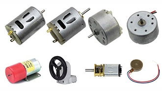
 This image shows a standard hobby-grade DC motor. Image courtesy of DigiKey.
 This image depicts the internal components of a servo motor. The housing contains a DC motor, control circuitry, and a gearbox.
Stepper motors are almost a middle ground between DC motors and servos, as they can rotate continuously like DC motors while still offering reliable angular accuracy similar to servos. They achieve this improved accuracy by moving in discrete steps instead of spinning freely. Controllers can advance the motor’s rotation in either direction by sending pulses, each of which turns the motor one step at a time. Stepper motors also offer high holding torque, allowing them to resist movement while stationary. To achieve this, they continuously draw current while holding position, which consumes more power and results in them running hotter than comparable DC motors. Additionally, step errors can accumulate over long periods, especially when steps are missed, and they cannot accelerate to higher RPMs as quickly. Compared to DC motors, stepper motors can be noisier, more expensive, and often produce less torque at higher RPMs. Because they offer excellent positional control and holding torque, stepper motors are perfect for machines such as 3D printers, CNC machines, plotters, and camera sliders.
 This image shows a standard stepper motor. Image courtesy of DigiKey.
How Stepper Motors Work
The basic operating principle of stepper motors is relatively straightforward. Internally, they consist of two parts that are responsible for their movement: the rotor and stator coils. The rotor is the part that spins, while the stator coils are arranged around it in fixed steps. These coils generate a magnetic field when energized, which causes the rotor to align itself with the active coils. Energizing the coils in a specific sequence makes the shaft spin in a controlled manner. Each time the controller advances to the next pattern, the rotor realigns itself with the new magnetic field, causing it to rotate by one step. The size of these steps depends on the motor design, with 0.9 or 1.8 degrees being the most common step angles.
 This figure illustrates how pulses can be sent to a stepper motor’s inputs to make the shaft turn in one direction. Image courtesy of Analog Devices.
Stepper motors are often divided into two major categories: unipolar and bipolar. Each coil in a unipolar stepper is electrically split into two halves. Although different arrangements exist, the center-tapped design is among the most common ones in hobby-grade unipolar stepper motors. This design utilizes a single winding with a center tap connection in the middle. The controller can energize either half of the coil independently to change the motor’s direction instead of reversing the current flow through the coil. For example, the motor can rotate one way by driving current between terminal A and the center tap or the other direction when current flows between terminal B and the center tap. This results in simpler driving circuitry, and unipolar motors are generally easier and cheaper to control, making them attractive for simpler or lower-cost applications. However, because only half of the winding is energized at a time, they usually produce lower torque compared to bipolar motors.
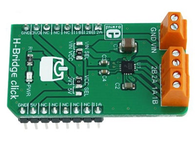
Bipolar stepper motors do not have those center taps, and the controller must instead reverse the current direction to change the magnetic field polarity. This is often achieved by using H-bridge-based driver circuitry. Even though bipolar stepper motors require more complex electronics, they energize the entire winding during operation, which generally results in higher torque and better efficiency. This type of stepper motor is common in modern CNC machines, 3D printers, and other higher-performance applications.
Stepper Motor Sizes and NEMA Ratings
Stepper motors are commonly characterized using NEMA (National Electrical Manufacturers Association) sizes, such as NEMA 17 or NEMA 23. This guideline describes the physical dimensions and mounting standards of the motor face rather than electrical characteristics or performance figures. Although the physical size often correlates with a motor’s torque or power, the NEMA size alone does not indicate motor strength, current draw, step angle, or quality. Two motors with the same NEMA rating can behave very differently depending on their internal construction and specifications.
NEMA 17 motors are common in DIY projects and widely used in 3D printers and small CNC machines. NEMA 23 motors are larger and common in CNC routers and more heavy-duty applications. Smaller NEMA 14 motors and below often appear in compact projects where space is more important than torque.
Controlling Stepper Motors
Stepper motors are typically not controlled by sending pulses from an MCU directly to the motor. Instead, they require additional external driving circuitry. These drivers handle the coil switching required to rotate the motor and protect the microcontroller from the higher currents involved. The exact type to use depends on whether the motor is unipolar or bipolar, but common hobby-grade driver modules include the A4988, DRV8825, and ULN2003.
Stepper motors can also draw significantly more current and require higher voltages to run than small DC motors or servos. Therefore, they typically require an external power supply that ensures continuous, stable power delivery.
On the software side, stepper motors are commonly controlled using libraries instead of manually generating control pulses. On Arduino, popular choices include the built-in Stepper library and AccelStepper for more advanced motion control.
Summary
Stepper motors differ from DC motors and servos in several ways, making them ideal for projects that require precise positioning and strong torque at low RPMs. Unlike regular DC motors, which spin continuously, stepper motors rotate in fixed increments that allow controllers to position them accurately.
Internally, stepper motors have a static coil and a spinning rotor. The stator coils generate magnetic fields when energized. These coils pull the rotor into fixed positions one step at a time. A controller can rotate the motor shaft by energizing these coils in a specific sequence.
Stepper motors are generally divided into unipolar and bipolar designs. Unipolar motors have center-tapped windings, which requires less complicated drive circuitry but usually yields less torque. Bipolar motors require more complex drivers that reverse current flow through the coils but deliver higher torque and efficiency. Popular hobby-grade driver modules include the A4988, DRV8825, and ULN2003.
Although stepper motors can be noisier, hotter, and less efficient at higher speeds than other motor types, their reliable positional accuracy and holding torque make them common in 3D printers, CNC machines, plotters, camera sliders, and many other motion-control systems.